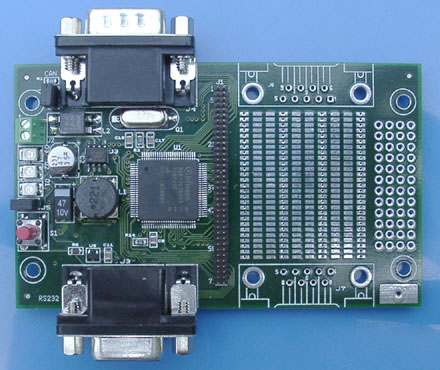
The XC164CS prototype board is designed for rapid development of small systems based on the XC164CS microcontroller from Infineon. Almost halve the board is available as prototype area and can be used for communication, sensor and/or actuator electronics. The board is meant for use as a XC164 starter kit for hardware and software development in a laboratory environment.
Small PCB (95 x 57 mm) with ground plane.
Infineon XC164CS 16-bit single-chip microcontroller
10 - 35 supply voltage DC/DC converter
D-Sub-9 RS232 connector
D-Sub-9 CAN connector
|
Reset push button
BSL jumper for bootstrap loader start up Yellow general purpose LED 72 way extension header for nearly all microcontroller ports Large double sided SMD prototyping area, optimised for SMD shapes:
Small 0.1” grid area for through-hole components:
Footprints for 2 additional D-Sub-9 connectors Large GND pad as measurement reference e.g. oscilloscope probe Programmed with firmware suitable for:
|
The board is programmed with software that contains an efficient RS232 to CAN converter and simple IO operation such as reading and writing IO pins. The board is delivered with a DLL and a windows test application.
Development environments and C compilers are available from Tasking, Keil and HighTec (GNU).
![]() XC164CS_ptb.pdf (213 kB)
XC164CS_ptb.pdf (213 kB)
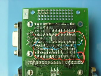
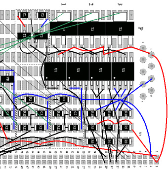
The image above shows a 24 V, 2 A brushless DC motor driver breadboarded on both sides of the prototyping area. The driver is controlled by the XC174CS CapCom6 module. Motor currents are sensed, amplified and AD converted. In total the circuit contains 85 parts of various shapes and about just as many wires. Before any component was soldered a detailed layout was made (see image below).
For further information please send an e-mail to: XC164CS@gerbo.nl
![]()
Copyright © 2004 Gerbo Technology